Last updated on January 29, 2017
Introduction
The growing accessibility of computer modeling software and 3D printing now makes it possible for someone with no traditional fabrication skills (like me) to create small, custom parts for their bike. I've designed several accessory mounts so far, and have been quite pleased with the results. These pieces have allowed me to install lights and computers in better locations on my bike than was possible with the original mounting hardware.
How I Do It
There are several software programs that can be used to model your designs. I use Autodesk's Fusion 360, since it is free for hobbyists to use. It also has plenty of tutorials, support documents and videos to help you get started. It took me a solid weekend to get the basics down, since manipulating a three-dimensional object on a two-dimensional screen isn't entirely intuitive.
To assist in the accuracy of my part design I also purchased a nice set of digital calipers. Since accessory mounts interface with both your bike and the part itself, getting accurate measurements of the dimensions at both ends is important for a good fit.
Once I have a design on the computer that I'm ready to have made, I export it into an STL file. This file I then upload to Shapeways, a 3D printing service. They will analyze the model to check that it is suitable for printing in the selected material, make it, and then ship it to me. It's that easy!
Rear Light Rack Bracket
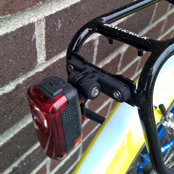
This piece is the first one I designed. I had recently purchased a helmet mount for my light so that I could go night riding on my mountain bike, and the mount had come with interchangeable attachments for either front or rear lights. Since I was only planning to use the front light attachment for my helmet, I decided to design a bracket that would allow me to affix the unused rear light attachment onto the back of my bicycle rack.
The bracket I came up with bolts through the two 50mm-spaced holes on the back of my rack. It features counterbores for the three bolt heads and the captive nut, rounded edges wherever possible for small material savings, and a large hollow in back for even more material savings (Shapeways charges based on volume.) The bases of the outer two tabs are kept thin to maintain enough flexibility for the bolt to have good clamping force across the whole stack of tabs. This way the light will remain pointing rearward, and won't pivot towards the ground. I haven't had to re-adjust it once!
Download the STL file of this model (270 KB)
Cyclocomputer Mount
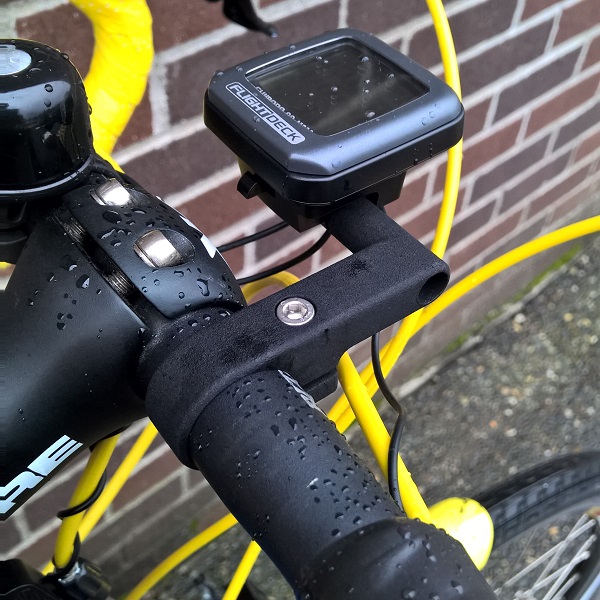
This is the second part I designed. The original handlebar clamp positioned my cyclocomputer's head unit so close to the the handlebar that it couldn't clear the faceplate of my stem, and had to be mounted off-center. Since the Shimano Flight Deck computer is long out of production with no aftermarket support, and because my handlebar's 26.0mm clamp diameter is no longer the prevailing standard, designing my own mount was the only solution.
This part also has counterbores for the clamp bolt, the captive nut, and the computer attachment screw. Since it uses a single-bolt clamp style, the clamp band needs to be flexible enough to open up and close around the diameter of the bar. I made the clamp band as thin as I dared, and even then it felt quite rigid as I pried it open to snap it in place, but it didn't break! Shapeways does call this material their "Strong & Flexible" plastic.
Download the STL file of this model (256 KB)
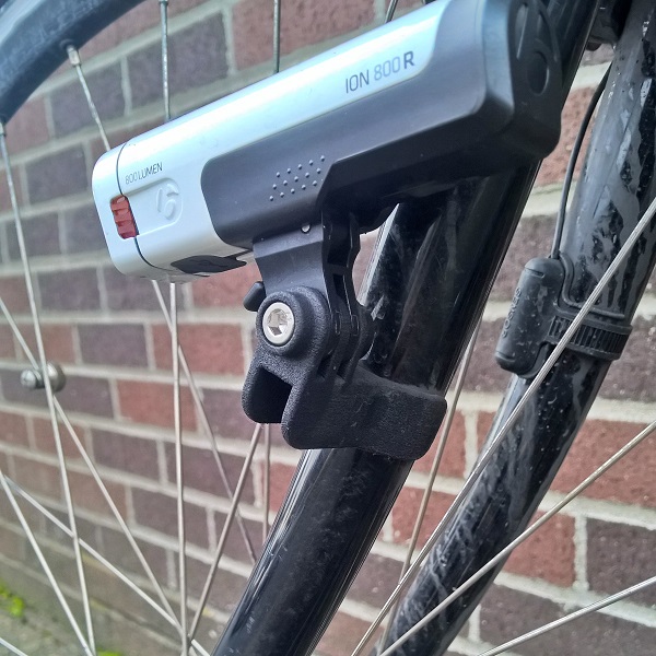
Front Light Fork Blade Mount
I also wanted a part that would allow me to bolt my front light directly into the mid-blade eyelet of my fork. I had already moved my light to this location, since the yellow cable housing coming out of my shift levers reflected brightly back into my eyes with it mounted to the handlebar. The silicone mounting strap included with my headlight had been perfectly adequate for this job, but with the success of my 3D-printed rear light bracket, I was eager to try a slightly more secure and custom solution.
The intermediate piece I chose my fork bracket to mate with is the Bontrager "High Ion Light Mount for Blendr," (Trek P/N W510438). It uses the same tabbed interface as the rear light attachment used on my rack bracket, so I designed a similar set of tabs again with counterbores for the bolt head and captive nut. These are attached to a platform cantilevered out from the fork, with a hole in the middle of the platform to pass the bolt through to the threaded fork eyelet.
As I only had a single eyelet to bolt into, I added two "wings" on either side of the eyelet hole, to prevent the light from rotating down and around the bolt. These wings are curved to match the 26mm diameter of my fork blades at that point, and wrap more than 180° around for extra security. The fork eyelet sits 2mm proud of the fork, so I recessed a bore around the eyelet hole to account for this, letting the mount sit perfectly flush with the surface of the fork.
Download the STL file of this model (539 KB)
Some Challenges
One obstacle I encountered early on was due to the fact that most of the accessory pieces which attach to my mounts are injection-molded. This means that many of the seemingly parallel faces are in fact tapered (for a great explanation of why, check out this video!) In this case, it means that the tabs for the light attachments are wedge-shaped in profile rather than perfectly rectangular.
Instead of matching these tapers in my parts, I chose dimensions that would average these differences out, my reasoning being that since the 3D-printed plastic is less dense than the injection-molded plastic, there would be some inherent "give" and room for approximation. Next time I won't do this. When installing the parts together, it was clear that the fit was tight at base of the gaps between the tabs, and loose at the top. However, once the bolt was passed through and tightened down, the gaps came together and everything was secure.
Another factor to consider is that the accuracy of these 3D prints is +/- 0.15mm. That means that if I design a counterbore for an 8.5mm bolt head to have exactly an 8.5mm diameter, it could end up anywhere between 8.35-8.65mm. If on the small end of this tolerance range, I could have an "interference fit" with the bolt head, which I don't want since I expect it to be able to spin as I tighten or loosen it. Therefore, I should specify a counterbore diameter of at least 8.65mm, and a bore of at least 5.15mm for the M5 bolt shaft itself to allow for the smallest possible result. Did I think to do this the first time? Nope, but I'm learning this as I go along.
Conclusion
There's definitely a limit to the applications of plastic parts on a bicycle (I won't be making 3D-printed chainrings anytime soon), but it's been fun dipping my toes into the product engineering process. I'm excited for the next project!
Model files for each of my parts are available for download above, so please feel free to check them out in a 3D viewer for a better look at some of the features I've described.